TPH F 80

TPH F 80/30

Beam Section Holder TPH F 80 W HCP
Group: A425
Form-fitting, reinforcing bracket for F 80 or F 80/30 Beam Sections
Mounting directly to the building structure or directly to the free-standing or concret-embedded profile
Overview of Types
General Information
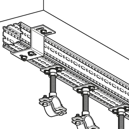
Interface element to connect 90° intersecting Beam Sections F80 or F 80/30. Alternatively the Beam Section Holder TPH may be used to connect only one beam section to an even surface with suitable wall anchors or with cast-in channel accessories.
Certification

Technical specifications
Material base body | steel |
Surface | HCP |
Corossion class | C4 |
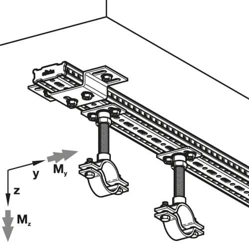
Load range
Type | -VX,perm. | VX,perm. | -VY,perm. | VY,perm. | -VZ,perm. | VZ,perm. |
TPH F 80/30 HCP | 14,40 kN | 14,40 kN | 28,10 kN | 28,10 kN | 18,30 kN | 18,30 kN |
TPH F 80 HCP | 14,40 kN | 14,40 kN | 28,10 kN | 28,10 kN | 18,30 kN | 18,30 kN |
Type | -MY,perm. | MY,perm. | -MZ,perm. | MZ,perm. |
TPH F 80/30 HCP | 1,2 kNm | 1,2 kNm | 1,2 kNm | 1,2 kNm |
TPH F 80 HCP | 1,2 kNm | 1,2 kNm | 1,2 kNm | 1,2 kNm |
The specified load values are permissible loads and contain the partial safety factors γ(M2) = 1,25 (DIN EN 1993-1-8:2010-12, chart 2.1) and γ(G) = 1,35 (DIN EN 1990:2010-12, chart A1.2(B)) for permanent actions.
Also available with DualShield for high corrosion protection within C5H environments.
Software
This product is available in the following software.


Installation
Connecting one Beam Section F80 or F 80/30 90° to another one by using 6 x Self Forming Screw FLS applied through all elongated holes.
Connecting to any other surface or member by using 2 x Self Forming Screws FLS through the two elongated holes on the top of the Beam Section Holder TPH F80 plus 2 appropriate fixing elements up to M12 through the two holes “d1”.