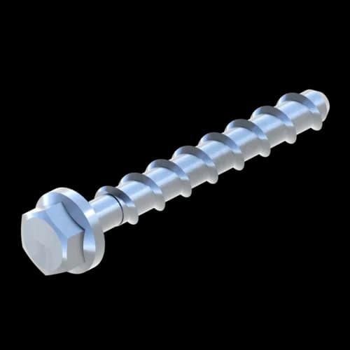
Screwbolt TSM-S
Group: 1407
Suitable for quick and safe fixation of Sikla Channel and further components to concrete and masonry ceilings or walls.
Approved for applications under seismic impact of category C1 and C2
Choose your country
Go to your local Sikla page and discover offers for your country or sales region:
Country
Group: 1407
Suitable for quick and safe fixation of Sikla Channel and further components to concrete and masonry ceilings or walls.
Approved for applications under seismic impact of category C1 and C2
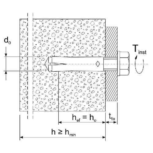
Screw in the bolt screw in pre-drilled hole. The special thread guarantees a mechanical form lock with the base material. Fine adjustment of depth is possible if the screwbolt is initially installed too deep.
Type 6x40: Only to be used as multiple fixing for non-load-bearing systems in concrete and prestressed concrete hollow plate ceilings.
PDF (1.77 MB)
PDF (3.7 MB)
PDF (233 KB)
PDF (4.09 MB)
PDF (100 KB)
PDF (564 KB)
Info | Type | L | Weight | Quantity | Part number | |
| TSM-S 6X 40 | 40,00 mm | 0,015 kg/pcs. | 100 pcs. | 115737 | ||
| TSM-S 6X 50 | 50,00 mm | 0,017 kg/pcs. | 100 pcs. | 115720 | ||
| TSM-S 6X 60 | 60,00 mm | 0,019 kg/pcs. | 100 pcs. | 115723 | ||
| TSM-S 6X 80 | 80,00 mm | 0,023 kg/pcs. | 100 pcs. | 115738 | ||
| TSM-S 6X100 | 100,00 mm | 0,027 kg/pcs. | 100 pcs. | 115739 | ||
| TSM-S 8X 50 | 50,00 mm | 0,032 kg/pcs. | 50 pcs. | 115731 | ||
| TSM-S 8X 60 | 60,00 mm | 0,036 kg/pcs. | 50 pcs. | 115732 | ||
| TSM-S 8X 70 | 70,00 mm | 0,04 kg/pcs. | 50 pcs. | 115734 | ||
| TSM-S 8X 80 | 80,00 mm | 0,044 kg/pcs. | 50 pcs. | 115735 | ||
| TSM-S 8X 90 | 90,00 mm | 0,048 kg/pcs. | 50 pcs. | 115736 | ||
| TSM-S 8X100 | 100,00 mm | 0,052 kg/pcs. | 50 pcs. | 115728 | ||
| TSM-S 8X120 | 120,00 mm | 0,058 kg/pcs. | 50 pcs. | 115729 | ||
| TSM-S 8X140 | 140,00 mm | 0,066 kg/pcs. | 50 pcs. | 115730 | ||
| TSM-S 10X 60 | 60,00 mm | 0,056 kg/pcs. | 50 pcs. | 115740 | ||
| TSM-S 10X 70 | 70,00 mm | 0,062 kg/pcs. | 50 pcs. | 115741 | ||
| TSM-S 10X 80 | 80,00 mm | 0,068 kg/pcs. | 50 pcs. | 115743 | ||
| TSM-S 10X 90 | 90,00 mm | 0,074 kg/pcs. | 50 pcs. | 115744 | ||
| TSM-S 10X100 | 100,00 mm | 0,08 kg/pcs. | 50 pcs. | 115745 | ||
| TSM-S 10X140 | 140,00 mm | 0,106 kg/pcs. | 50 pcs. | 115746 | ||
| TSM-S 12X110 | 110,00 mm | 0,12 kg/pcs. | 25 pcs. | 115747 | ||
| TSM-S 12X130 | 130,00 mm | 0,136 kg/pcs. | 25 pcs. | 115748 | ||
| TSM-S 12X150 | 150,00 mm | 0,152 kg/pcs. | 25 pcs. | 115749 | ||
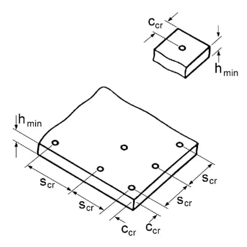
Suitable for quick and safe fixation of Sikla Channels or Mounting Plates to concrete and masonry ceilings or walls. To be applied in dry rooms not exposed to high corrosion resistance requirements. European Technical Assessment for anchoring in cracked and non-cracked concrete (Option 1). European Technical Assessment for multiple use for non-structural systems in concrete and precast pre-stressed hollow core slabs. Approved for applications under seismic impact of category C1 and C2 (Types, diameters and anchoring depths are shown in the 'type overview' and ETA-16/0655. Also fixes into pressure-resistant natural stones and different solid bricks (not part of ETA approval / guideline). Flexible use for high or standard load performances due to 3 anchoring depths. Small edge and axial distance due to low expansion pressure. Low drillling effort.
Certification


ETA-16/0655 and ETA-16/0656
Primary element material | steel |
Surface finish | electro galvanized (Fe//Zn) |
Corrosion protection class | C2 |
For load values, see additional documents.
Further technical information (load capacities under fire exposure, appr. loads in further concrete classes and precast pre-stressed hollow core slabs) are shown in the download area.
The following types are procured on an order-by-order basis and therefore have a delivery date on request: 6x100, 8x90, 8x100, 8x120, 8x140, 10x80, 10x90, 10x100, 10x140, 12x110
Software
This product is available in the following software.